Rain Water Harvesting for the Individual Houses
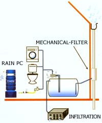
Roof top rain water can be diverted to the existing open / bore well. Along with this, rain water available in the open spaces around the building may be recharged into the ground through the following simple effective methods.
Percolation pits (Small houses)
Recharge Trench (Big houses / Apartments)
Recharge wells (Large buildings / industries)
Recharge Trench (Big houses / Apartments)
Recharge wells (Large buildings / industries)
Based on the size /area of the building and the underlying lithological nature of the formation the said methods may be used either individually or in combinations.
To enhance nature recharge of rain water avoid pavements since unpaved surfaces have more percolation rate.
Various Methods of Recharging In Individual Houses
Various Methods of Recharging In Individual Houses
 |
Components of Rooftop Rainwater Harvesting System
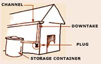
In domestic Rooftop Rainwater Harvesting Systems rainwater from the house roof is collected in a storage vessel or tank for use during the periods of scarcity. Usually these systems are designed to support the drinking and cooking needs of the family at the doorstep. Such a system usually comprises a roof, a storage tank and guttering to transport the water from the roof to the storage tank. In addition, a first flush system to divert the dirty water which contains roof debris collected on the roof during non-rainy periods and a filter unit to remove debris and contaminants before water enters the storage tank are also provided. Therefore, a typical rooftop Rainwater Harvesting System comprise of following components:
· Roof catchment
· Gutters
· Down pipe and first flush pipe
· Filter unit
· Storage tank
· Collection pit
· Roof catchment
· Gutters
· Down pipe and first flush pipe
· Filter unit
· Storage tank
· Collection pit
Among the above components, storage tank is the most expensive and critical component. The capacity of the storage tank determines the cost of the system and reliability of the system for assured water supply. Following is the brief description of each component with a study of different materials used for each component.
Roof Catchment:
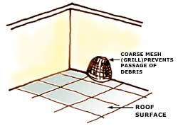
The roof of the house is used as the catchment for collecting the rainwater. The style, construction and material of the roof affect its suitability as a catchment. Roofs made of corrugated iron sheet, asbestos sheet, tiles or concrete can be utilized as such for harvesting the rainwater. But thatched roofs are not suitable as it gives some colour to water and also the water carries pieces of roof material (such as palm leaves).
The roof of the house is used as the catchment for collecting the rainwater. The style, construction and material of the roof affect its suitability as a catchment. Roofs made of corrugated iron sheet, asbestos sheet, tiles or concrete can be utilized as such for harvesting the rainwater. But thatched roofs are not suitable as it gives some colour to water and also the water carries pieces of roof material (such as palm leaves).
Gutters:
Gutters are channels fixed to the edges of roof all around to collect and transport the rainwater from the roof to the storage tank. Gutters can be prepared in semi-circular and rectangular shapes as shown in figures. Locally available material such as plain galvanized iron sheet can be easily folded to required shapes to prepare semi-circular and rectangular gutters. Semi-circular gutters of PVC material can be readily prepared by cutting the PVC pipes into two equal semi-circular channels. Bamboo poles can also be used for making gutters if they are locally available in sufficient quantity. Use of such locally available materials reduces the overall cost of the system.
Gutters are channels fixed to the edges of roof all around to collect and transport the rainwater from the roof to the storage tank. Gutters can be prepared in semi-circular and rectangular shapes as shown in figures. Locally available material such as plain galvanized iron sheet can be easily folded to required shapes to prepare semi-circular and rectangular gutters. Semi-circular gutters of PVC material can be readily prepared by cutting the PVC pipes into two equal semi-circular channels. Bamboo poles can also be used for making gutters if they are locally available in sufficient quantity. Use of such locally available materials reduces the overall cost of the system.
Downpipe and First Flush Pipe:
Downpipe:
Down pipe is the pipe, which carries the rainwater from the gutters to the storage tank. Down pipe is joined with the gutters at one end, and the other end is connected to the filter unit of the storage tank as shown in figure below. PVC or GI pipes of diameter 50 mm to 75 mm (2 inch to 3 inch) are commonly used for down-pipe. Bamboo can also be used wherever available in suitable size.
Downpipe:
Down pipe is the pipe, which carries the rainwater from the gutters to the storage tank. Down pipe is joined with the gutters at one end, and the other end is connected to the filter unit of the storage tank as shown in figure below. PVC or GI pipes of diameter 50 mm to 75 mm (2 inch to 3 inch) are commonly used for down-pipe. Bamboo can also be used wherever available in suitable size.
First Flush Pipe:
Debris, dirt and dust collect on the roofs during non-rainy periods. When the first rains arrive, this unwanted material will be washed into the storage tank. This caused contamination of water collected in the storage tank thereby rendering it unfit for drinking and cooking purposes.
Therefore, a first flush system is incorporated in the Rooftop Rainwater Harvesting Systems to dispose off the 'first flush' water so that it does not enter the tank. There are two such simple systems. One is based on a simple manually operated arrangement, whereby, the down pipe is moved away from the tank inlet and replaced again once the first flush water has been disposed.
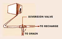
In another simple and semi-automatic system, a separate vertical pipe is fixed to the down pipe with a valve provided below the "T" junction as shown in figure.
After the first rain is washed out through first flush pipe, the valve is closed to allow the water to enter the down pipe and reach the storage tank.
Debris, dirt and dust collect on the roofs during non-rainy periods. When the first rains arrive, this unwanted material will be washed into the storage tank. This caused contamination of water collected in the storage tank thereby rendering it unfit for drinking and cooking purposes.
Therefore, a first flush system is incorporated in the Rooftop Rainwater Harvesting Systems to dispose off the 'first flush' water so that it does not enter the tank. There are two such simple systems. One is based on a simple manually operated arrangement, whereby, the down pipe is moved away from the tank inlet and replaced again once the first flush water has been disposed.
In another simple and semi-automatic system, a separate vertical pipe is fixed to the down pipe with a valve provided below the "T" junction as shown in figure.
After the first rain is washed out through first flush pipe, the valve is closed to allow the water to enter the down pipe and reach the storage tank.
Filter Unit:
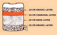
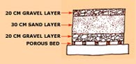
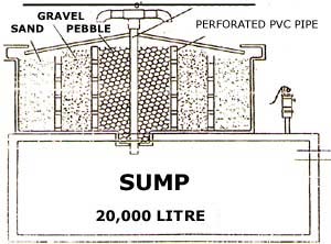
The filter unit is a container or chamber filled with filter media such as coarse sand, charcoal, coconut fibre, pebbles and gravels to remove the debris and dirt from water that enters the tank. The container is provided with a perforated bottom to allow the passage of water. The filter unit is placed over the storage tank. Commonly used filters are of two types. One is a ferrocement filter unit, which is comparatively heavy and the other is made of either aluminium or plastic bucket. The latter is readily available in market and has the advantage of ease in removing, cleaning and replacing.
Another simple way of filtering the debris and dust particles that came from the roof along with rainwater is to use a fine cloth as filter media. The cloth, in 2 or 3 layers, can be tied to the top of a bucket or vessel with perforations at the bottom.
The filter unit is a container or chamber filled with filter media such as coarse sand, charcoal, coconut fibre, pebbles and gravels to remove the debris and dirt from water that enters the tank. The container is provided with a perforated bottom to allow the passage of water. The filter unit is placed over the storage tank. Commonly used filters are of two types. One is a ferrocement filter unit, which is comparatively heavy and the other is made of either aluminium or plastic bucket. The latter is readily available in market and has the advantage of ease in removing, cleaning and replacing.
Another simple way of filtering the debris and dust particles that came from the roof along with rainwater is to use a fine cloth as filter media. The cloth, in 2 or 3 layers, can be tied to the top of a bucket or vessel with perforations at the bottom.
Storage Tank:
Storage tank is used to store the water that is collected from the Rooftops. Common vessels used for small scale water storage are plastic bowls, buckets, jerry cans, clay or ceramic jars, cement jars, old oil drums etc. For storing larger quantities of water the system will usually require a bigger tank with sufficient strength and durability.
There are unlimited number of options for the construction of these tanks with respect to the shape (cylindrical, rectangular and square), the size (Capacity from 1,000 lt. to 15,000 lt. or even higher) and the material of construction (brickwork, stonework, cement bricks, ferrocement, plain cement concrete and reinforced cement concrete). For domestic water needs, taking the economy and durability of tanks into consideration, ferrocement tanks of cylindrical shape in capacities ranging between 4,000 lt. and 15,000 lt. are most suitable. Plain cement concrete and reinforced cement concrete are used for tank capacities usually more than 50,000 lt. Brick, stone, cement brick may be used for capacities ranging between 15,000 lt. to 50,000 lt.
The ferrocement tanks are usually constructed above ground level because of the advantages, such as, a) ease in finding structural problems/leaks, b) easy to maintain and clean and c) easy to draw water. It is difficult to detect the leaks and take corrective measures in case of underground tanks. Water from underground tanks cannot be drawn by gravity. Some kind of manual or power lifting devices need to be used for drawing the water. Further, in coastal areas, underground tanks are prone to water contamination due to fluctuation in groundwater table and leakage of stored water.
The storage tank is provided with a cover on the top to avoid the contamination of water from external sources. The cover will be in dome shape having a raise of about 20-30 cm. in the middle. The dome is provided with two circular openings, one for manhole and another for accommodating the filter. A lid covers the manhole avoiding exposure of stored water to the outside environment. The storage tank is provided with pipe fixtures at appropriate places to draw the water, to clean the tank and to dispose of the excess water. They are named tap or outlet, drainpipe and over flow pipe respectively. PVC or GI pipes of diameter 20 mm to 25 mm (¾ inch to 1 inch) are generally used for this purpose.
Storage tank is used to store the water that is collected from the Rooftops. Common vessels used for small scale water storage are plastic bowls, buckets, jerry cans, clay or ceramic jars, cement jars, old oil drums etc. For storing larger quantities of water the system will usually require a bigger tank with sufficient strength and durability.
There are unlimited number of options for the construction of these tanks with respect to the shape (cylindrical, rectangular and square), the size (Capacity from 1,000 lt. to 15,000 lt. or even higher) and the material of construction (brickwork, stonework, cement bricks, ferrocement, plain cement concrete and reinforced cement concrete). For domestic water needs, taking the economy and durability of tanks into consideration, ferrocement tanks of cylindrical shape in capacities ranging between 4,000 lt. and 15,000 lt. are most suitable. Plain cement concrete and reinforced cement concrete are used for tank capacities usually more than 50,000 lt. Brick, stone, cement brick may be used for capacities ranging between 15,000 lt. to 50,000 lt.
The ferrocement tanks are usually constructed above ground level because of the advantages, such as, a) ease in finding structural problems/leaks, b) easy to maintain and clean and c) easy to draw water. It is difficult to detect the leaks and take corrective measures in case of underground tanks. Water from underground tanks cannot be drawn by gravity. Some kind of manual or power lifting devices need to be used for drawing the water. Further, in coastal areas, underground tanks are prone to water contamination due to fluctuation in groundwater table and leakage of stored water.
The storage tank is provided with a cover on the top to avoid the contamination of water from external sources. The cover will be in dome shape having a raise of about 20-30 cm. in the middle. The dome is provided with two circular openings, one for manhole and another for accommodating the filter. A lid covers the manhole avoiding exposure of stored water to the outside environment. The storage tank is provided with pipe fixtures at appropriate places to draw the water, to clean the tank and to dispose of the excess water. They are named tap or outlet, drainpipe and over flow pipe respectively. PVC or GI pipes of diameter 20 mm to 25 mm (¾ inch to 1 inch) are generally used for this purpose.
Collection Pit:
A small pit is dug in the ground, beneath the tap of the storage tank and constructed in brick masonry to make a chamber, so that a vessel could be conveniently placed beneath the tap for collecting water from the storage tank. A small hole is left at the bottom of the chamber, to allow the excess water to drain-out without stagnation. Size of collection pit shall be 60 cm x 60 cm x 60 cm.
A small pit is dug in the ground, beneath the tap of the storage tank and constructed in brick masonry to make a chamber, so that a vessel could be conveniently placed beneath the tap for collecting water from the storage tank. A small hole is left at the bottom of the chamber, to allow the excess water to drain-out without stagnation. Size of collection pit shall be 60 cm x 60 cm x 60 cm.